
When engineers and plant managers think about power factor correction, they often picture large high-voltage capacitor banks at the main incomer, which is nothing but a substation-level solution for a substation-level problem.
But the reality of most industrial and commercial power systems is that a significant portion of the reactive load originates at the low voltage (LV) level, which lies in motor control centres, distribution boards, lighting panels, and individual machine connections.
Correcting power factor as close to the load as possible is almost always more effective than correcting it at a higher voltage level. The advantage is reduced reactive current in the LV cables, which reduces transformer losses and frees up capacity throughout the distribution system. And the primary tool for doing this is the LT capacitor bank.
This guide covers everything you need to know about LT capacitor banks: what they are, where they are used, how to choose between fixed and automatic configurations, when a series reactor is essential, and how to specify the right solution for your load profile.
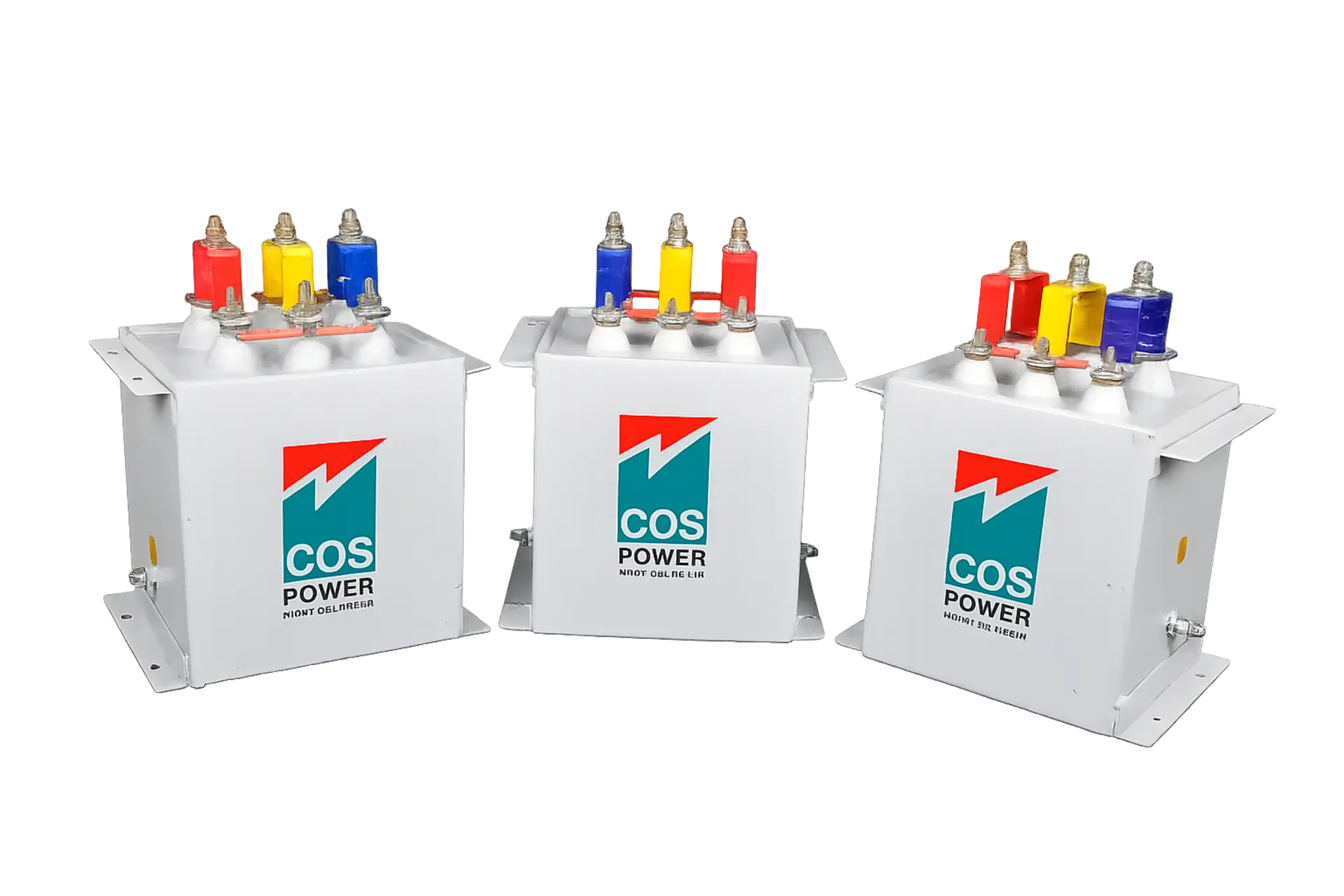
An LT (Low Tension) capacitor bank is a bank of capacitors connected to a low voltage electrical network. It typically operates at 415V or 440V in Indian industrial and commercial installations to supply reactive power locally. By supplying reactive (capacitive) current at the point of load, the capacitor bank reduces the reactive current that would otherwise have to be drawn from the grid or the upstream transformer.
The result is an improved power factor at the LV bus: less reactive current in LV cables, lower I²R losses, reduced kVAh consumption, and a lower maximum demand reading on the utility meter.
LT capacitor banks can be deployed as standalone fixed units or as part of an Automatic Power Factor Correction (APFC) panel where a microcontroller-based relay monitors the power factor in real time and switches capacitor steps in and out automatically as the load changes.
LT capacitor banks are used across a wide range of industrial, commercial, and infrastructure applications wherever low-voltage reactive power correction is needed:
• Mills and manufacturing plants like paper mills, textile mills, food processing units
• Steel rolling mills and metal fabrication units which have high reactive demand from large motors and furnaces
• Pharmaceutical and chemical industries which are continuous process plants with consistent reactive loads
• Commercial buildings like offices, shopping centres, IT parks with large HVAC and UPS loads
• Five-star hotels and hospitals where power quality directly affects sensitive equipment and patient safety
• Water treatment and irrigation projects with large pump motors and significant reactive demand
• Coal handling and mining projects with variable motor loads requiring automatic correction
A fixed capacitor bank provides a constant KVAR output regardless of how the load changes. It is appropriate where the reactive demand is relatively stable and predictable. For example, a motor that runs continuously at a consistent load, or a transformer that feeds a steady process load.
Fixed banks are simpler, lower cost, and require less maintenance than automatic systems. Their limitation is that they cannot adapt to changing loads. Over-correction at light load can push the power factor leading, which can cause its own set of problems, including voltage rise and potential equipment damage.
An Automatic Power Factor Correction panel uses a power factor relay to monitor the LV bus continuously and switch capacitor banks in and out using contactors as the load changes. This keeps the power factor consistently above the target threshold regardless of load variations.
APFC panels are suitable for loads that fluctuate moderately. For example, a mix of motors with varying duty cycles, or a facility with significantly different day and night load profiles. The contactor switching is cost-effective and reliable for loads that change relatively slowly.
For loads that change very rapidly like arc furnaces, rolling mills, welding machines, or equipment with frequent motor starts, contactor switching is too slow. A Real-Time Power Factor Correction (RTPFC) panel uses thyristor switches instead of contactors, enabling switching in milliseconds rather than seconds.
Thyristor switching also eliminates the transient voltage spikes and inrush current surges associated with contactor switching, making RTPFC panels the right choice for sensitive environments where switching transients cannot be tolerated.
An LT series reactor connects in series with the capacitor bank and is one of the most important, yet most frequently omitted elements in a well-specified LT power factor correction system.
In any network containing non-linear loads (variable frequency drives (VFDs), rectifiers, UPS systems, or any load generating harmonic currents), the capacitor bank presents low impedance to harmonic frequencies. Without a series reactor, these harmonic currents flow freely into the capacitor bank, causing overheating, dielectric stress, and premature failure.
The series reactor detunes the capacitor bank from the network harmonic frequencies, blocking harmonic currents from entering the capacitors. It also limits the inrush current when the capacitor bank is switched in, reducing stress on contactors, thyristors, and connected equipment.
Specifying an LT capacitor bank correctly requires more than dividing a target KVAR by the number of steps. The key inputs are:
• Current power factor and target power factor: Determines the total KVAR required
• Load profile: Stable or fluctuating determines fixed vs APFC vs RTPFC
• Harmonic content (THD): Determines whether a series reactor is required and at what tuning factor
• Voltage level: 415V or 440V, and whether there are voltage variations that affect capacitor rating
• Available panel space and installation environment: Indoor, outdoor, ambient temperature
At Cospower, every LT power factor correction solution begins with a site assessment and, where harmonic distortion is a concern, a harmonic survey. Getting the specification right at the outset avoids costly retrofits, premature failures, and the persistent power quality problems that come with an undersized or incorrectly specified system.
LT capacitor banks are the workhorses of low voltage power factor correction. When correctly specified — with the right KVAR rating, the right switching technology, and a series reactor where harmonic levels demand one — they deliver reliable, long-term performance that directly reduces electricity costs, extends the life of electrical assets, and keeps the facility within utility power factor requirements.
The key is getting the specification right. A well-engineered LT PF correction system is not a commodity purchase — it is an engineered solution, and the quality of the engineering determines the quality of the result.
CTA
Need help specifying the right LT capacitor bank or APFC panel for your facility? Talk to Cospower’s engineers.